289 Results
View results:
Sort by:

The data exchange between RFEM 6 and Allplan can be done using various file formats. This article describes the data exchange of a determined surface reinforcement using the ASF interface. This allows you to display the RFEM reinforcement values as level curves or colored reinforcement images in Allplan.

Lateral-Torsional Buckling (LTB) is a phenomenon that occurs when a beam or structural member is subjected to bending and the compression flange is not sufficiently supported laterally. This leads to a combination of lateral displacement and twisting. It is a critical consideration in the design of structural elements, especially in slender beams and girders.

When wind-induced surface pressures on a building are available, they can be applied on a structural model in RFEM 6, processed by RWIND 2, and used as wind loads for static analysis in RFEM 6.

RWIND 2 and RFEM 6 can now be used to calculate wind loads from experimentally measured wind pressures on surfaces. Basically, two interpolation methods are available to distribute pressures measured in isolated points across the surfaces. The desired pressure distribution can be achieved using the appropriate method and parameter settings.

Both the determination of natural vibrations and the response spectrum analysis are always performed on a linear system. If nonlinearities exist in the system, they are linearized and thus not taken into account. They are caused by, for example, tension members, nonlinear supports, or nonlinear hinges. This article shows how you can handle them in a dynamic analysis.

The automatic surface reinforcement design process determines a surface reinforcement that covers the required amount of reinforcement.

If you want to use a pure surface model, for example, when determining the internal forces and moments, but the structural component is still designed on the member model, you can take advantage of a result beam.

In many frame and truss structures, it is no longer sufficient to use a simple member. You often have to consider cross-section weakenings or openings in solid beams. In such cases, you can use the "Surface Model" member type. It can be integrated into the model like any other member and offers all the options of a surface model. The present technical article shows the application of such a member in an existing structural system and describes the integration of member openings.

When a concrete slab is set upon the top flange, its effect is like a lateral support (composite construction), preventing problems of torsional buckling stability. If there is a negative distribution of the bending moment, the bottom flange is subjected to compression and the top flange is under tension. If the lateral support given by the stiffness of the web is insufficient, the angle between the bottom flange and the web intersection line is variable in this case so that there is a possibility of distortional buckling for the bottom flange.

For the stability verification of members using the equivalent member method, it is necessary to define effective or lateral-torsional buckling lengths in order to determine a critical load for stability failure. In this article an RFEM 6-specific function is presented, by which you can assign an eccentricity to the nodal supports and thus influence the determination of the critical bending moment considered in the stability analysis.

Surfaces in building models can be of many different sizes and shapes. All surfaces can be considered in RFEM 6 because the program allows to define different materials and thicknesses as well as surfaces with different stiffness and geometry types. This article focuses on four of these surface types: rotated, trimmed, without thickness, and load transfer.

In computational fluid dynamics (CFD), complex surfaces that are not completely solid can be modeled using porous or permeability media. In the actual world, examples of such things include windbreak fabric structures, wire meshes, perforated facades and claddings, louvers, tube banks (stacks of horizontal cylinders), and so on.

As for the previous generations of Dlubal programs, an integrated interface with Autodesk Revit is now also available for RFEM 6 and RSTAB 9. This article will provide some general information about the interface as well as the Dlubal-relevant structural objects and parameters in Revit.

Spreadsheet programs like MS EXCEL are very popular with engineers because they allow you to simply automatize your calculations and quickly output the results. Therefore, combining MS EXCEL used as a graphical interface with Dlubal's WebService API is an obvious choice. By using the free xlwings library for Python, you can control EXCEL, and read and write values. The functionality is described in the following, using an example.

Line releases are special objects in RFEM 6 that allow structural decoupling of objects connected to a line. They are mostly used to decouple two surfaces that are not rigidly connected or transferring only compressive forces at the common boundary line. By defining a line release, a new line is generated at the same place which transfers only the locked degrees of freedom. This article will show the definition of line releases in a practical example.
RWIND 2 is a program for generating wind loads based on CFD (Computational Fluid Dynamics). The wind flow numerical simulation is generated around any building, including irregular or unique geometry types, to determine the wind loads on surfaces and members. RWIND 2 can be integrated with RFEM/RSTAB for the structural analysis and design or as a stand-alone application.

In RFEM 6 it is possible to define multilayer surface structures with the help of the “Multilayer Surfaces” add-on. Hence, if you have activated the add-on in the model’s Base Data, it is possible to define layer structures of any material model. You can also combine material models of, for example, isotropic and orthotropic materials.

This article shows you how to create contacts between two or more parallel surfaces by controlling the transfer of forces between them.

This article will show you how to properly consider the connection between surfaces that touch each other on one line with the help of line hinges in RFEM 6.
This article will introduce to you the “Surface Results Adjustments” in RFEM 6, corresponding to the "Average Region" function implemented in RFEM 5.
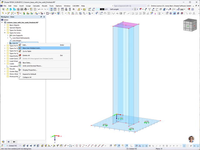
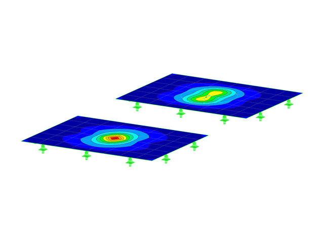
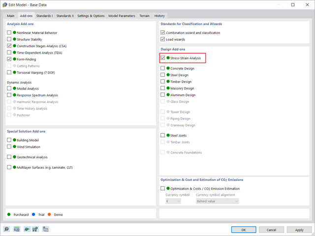
In RFEM 6, it is possible to define line welds between surfaces and calculate the weld stresses using the Stress-Strain Analysis add-on. This article will show you how to do it.

A standard scenario in timber member construction is the ability to connect smaller members by means of bearing on a larger girder member. Additionally, member end conditions may include a similar situation where the beam is bearing on a support type. In either scenario, the beam must be designed to consider the bearing capacity perpendicular to the grain according to NDS 2018 Sec. 3.10.2 and CSA O86:19 Clauses 6.5.6 and 7.5.9. In general structural design software, it is typically not possible to carry out this full design check, as the bearing area is unknown. However, in the new generation RFEM 6 and Timber Design add-on, the added 'design supports' feature now allows users to comply with the NDS and CSA bearing perpendicular to the grain design checks.
This article shows how to manage the input data for member and surface design configurations within the Stress-Strain Analysis add-on.

The optimal scenario in which punching shear design according to ACI 318-19 [1] or CSA A23.3:19 [2] should be utilized is when a slab is experiencing a high concentration of loading or reaction forces occurring at one single node. In RFEM 6, the node in which punching shear is an issue is referred to as a punching shear node. The causes of these high concentration of forces can be introduced by a column, concentrated force, or nodal support. Connecting walls can also cause these concentrated loads at wall ends, corners, and ends of line loads and supports.

The dynamic analysis in RFEM 6 and RSTAB 9 is divided into several add-ons. The Modal Analysis add-on is a prerequisite for all other dynamic add-ons, since it performs the natural vibration analysis for member, surface, and solid models.
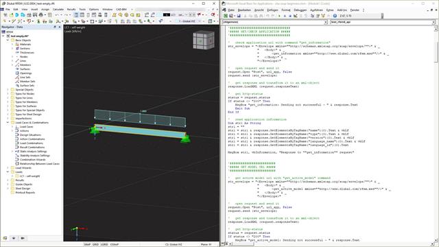
Webservice is a communication between machines and programs. This communication is provided via the network and can, therefore, be used by any program that can send and receive strings via the HTTP protocol. RFEM 6 and RSTAB 9 provide an interface based on these cross-platform webservices. This tutorial shows the basics using the VBA programming language.

The Construction Stages Analysis (CSA) add-on allows for the design of member, surface, and solid structures in RFEM 6 considering the specific construction stages associated with the construction process. This is important since buildings are not constructed all at once, but by gradually combining individual structural parts. The single steps in which structural elements, as well as loads, are added to the building are called construction stages, whereas the process itself is called a construction process.
Thus, the final state of the structure is available upon completion of the construction process; that is, all the construction stages. For some structures, the influence of the construction process (that is, all the individual construction stages) might be significant and it should be considered so that errors in the calculation are avoided. A general overview of the CSA add-on is given in the Knowledge Base article titled “Consideration of Construction Stages in RFEM 6”.

RWIND 2 is a program for generating wind loads based on CFD (Computational Fluid Dynamics). The wind flow numerical simulation is generated around any building, including irregular or unique geometry types, to determine the wind loads on surfaces and members. RWIND 2 can be integrated with RFEM/RSTAB for the structural analysis and design or as a stand-alone application.

To perform deflection analysis in the right manner, it is important to “inform” the program about the exact support conditions of the element of interest. The definition of design supports in RFEM 6 will be shown for a reinforced concrete member set.

In accordance with Sect. 6.6.3.1.1 and Clause 10.14.1.2 of ACI 318-19 and CSA A23.3-19, respectively, RFEM effectively takes into consideration concrete member and surface stiffness reduction for various element types. Available selection types include cracked and uncracked walls, flat plates and slabs, beams, and columns. The multiplier factors available within the program are taken directly from Table 6.6.3.1.1(a) and Table 10.14.1.2.